

The aim of good lifting practice is to ensure that the load is safe and, when lifted, is as secure in the air as it was on the ground. The general procedure that follows can be applied to any lifting operation, regardless of the type of lifting appliance or the method of attaching the load to the appliance.
The terms “rigging” and “slinging,” which have been used throughout, are most commonly used to refer to the methods by which the weight is fastened to the lifting apparatus.
1) It is important to make sure that no item is lifted heavier than its specified safe working load (SWL). When in doubt about the weight of the load or the load applied to a particular piece of equipment, load sensing devices should be employed to ascertain the load’s weight and the center of gravity’s position with respect to the lifting (pick-up) points.
2) Identify the most efficient way to lift and sling the load; the equipment you select should be secure; no piece of lifting equipment should be overloaded because of the weight of the load or the weight and method of slinging; and it should only be used in accordance with the manufacturer’s instructions; it should not be modified or used for any other purpose without the manufacturer’s or another competent design authority’s approval.
3) The load will generally swing and may become unstable if its center of gravity is not vertically beneath the crane hook at any point or if its center of gravity is higher than the point where the slings are attached to the load. The slinging method must guarantee that the load is balanced, that it does not abruptly or violently change its attitude when lifted, and that it remains stable throughout the lift.
Also read more: Center of gravity toolbox talk
4) Packing may be required between the sling and the load, depending on the slinging method chosen. It is important to make sure that neither the lifting equipment nor the weight may injure each other.
5) The lifting equipment should go through a pre-use examination to make sure there are no obvious faults before being used.
6) If, as determined by the risk assessment, ropes or “tag lines” must be used to control the load once it is in the air; this is particularly recommended for long loads, to which tag lines must be attached at one or both ends to facilitate the control of rotational movement; the tag line must be sufficiently long to prevent the operator(s) from having to stand beneath the load during the lift; rigidity forbids the use of tag lines for any other purpose than controlling the rotation of the load.
7) The lift design must take into account any obstacles that may need to be avoided, such as overhead electrical lines, pipework, or other lifting activities.
8) Prior to starting the operation, a suitable landing site needs to be prepared. It should be large enough to support the weight of the load, and the operative needs to be aware of any underground ducts, suspended floors, cellars, or other structures that could reduce the floor’s capacity to support the weight. It might also be necessary to provide suitable landing pads, like timber bearers, to allow the slings to be removed from under the load.
9) A lot of resistance from joints or seals should be separated in some other way. Before the lifting starts, make sure the weight is free to be raised and not hampered by fastening bolts, jigs, etc.
10) Ensure that any loose cargo parts are either removed or securely fastened using the slinging technique or another approach, such as secondary positive holding devices, containers, or bindings.
11) All those involved in the lifting operations and assigned tasks under the lift plan must have a clear means of communication; hand signals are preferable to voice signals, particularly in circumstances where noise might interfere. standard crane signals are provided; in the event that the lifting operation’s personnel are not accustomed to working together, they should confirm in advance that they are all familiar with the signal system; and in the event that voice communication is employed, a protocol should be established to avoid miscommunication.
12) If it is not possible to keep everyone away from the area where operations are occurring, then safety measures to protect people in the danger zone must be taken, such as secondary load restraints to secure the load in the event that the primary fails. No one should be under a suspended load unless it is absolutely necessary.
13) For all lifting operations, the load should only be lifted a nominal distance in the first instance. This trial lift allows the operative to check and confirm the balance, stability, and general security of the load while it is in a relatively safe position. If there are any discrepancies, the load should be lowered and the slinging revised within the bounds of use. The sequence of trial lift and adjustment should be repeated until the operative is satisfied that the load is balanced, stable, and secure.

14) The trial landing procedure is very similar; before lowering the load, it should be stopped a short distance above the landing site to allow the operative to steady it, check its position and the position of any landing pads, etc., and to ensure that all personnel are clear of the danger area. If the load is not safe and stable, it should be lifted slightly to allow the landing blocks, etc., to be adjusted and lowered again.
THE weight SHOULD NOT BE LOWERED SO AS TO TRAP THE SLINGS, AS THIS MAY RESULT IN SERIOUS DAMAGE TO THEM; instead, it should be repeated in accordance with the trial lift method until the operator is satisfied that the weight is securely landed.
15) The worker should never use the lifting appliance to drag a sling out from under a weight; instead, the worker should manually remove the sling legs after correctly laying the load down to prevent damage.
16) If the equipment is no longer needed once the lifting operation is finished, it should be put back into its designated storage.
17) To reduce the possibility of slings unintentionally hooking onto nearby items or striking someone, the sling legs should be hooked back into the top terminal fitting if the slings are to be left on the lifting appliance for additional lifts.
Endless chain slings: Since endless chain slings are made specifically for use in choke hitches, they do not need to be de-rated when used in these situations. However, endless rope slings should be reduced to 0.8 x WLL. Endless slings are typically used in choke hitches and may need to be de-rated in accordance with applicable standards, the manufacturer, or the supplier.
It is presumed that the radii around which the sling passes at the places of connection to the load and the lifting appliance are sufficiently large to prevent sling damage.
Basic Principles
(1) The sling and how it is used should be appropriate for the load;
(2) the sling and the load’s attachment method should be secure;
(3) no part of the sling should be overloaded, either by the load’s weight or by the slinging technique;
(4) The slinging technique should guarantee that the load is secure and that it will not fall from the sling; (5) the load should be stable and balanced and should not abruptly change its attitude when lifted; and (6) the load cannot harm the sling or cause damage to the sling.

Although the uniform load method was introduced to some standard practices, some manufacturers continue to rate and mark multipurpose slings using the trigonometric method, which allows for a variation in the working load limit as the angle to the vertical (or the angle between the sling legs) varies. This method is the one that was previously used in many standards, but in order to use it for multipurpose applications, the operative must calculate the SWLs at various angles for each size of chain, rope, etc. Additionally, the operative must be trained in determining a range of angles, and there is an inherent danger that the sling may be overloaded if misjudged.
This method should only be applied to slings intended for single-purpose use or in compliance with applicable national standards that allow it. Slings marked for multipurpose use will not comply with those standards that have adopted the uniform load method.
Working load limits are derived from the following:
Single leg sling = 1 x WLL of a single leg
Two-leg sling = 2 x WLL of a single leg x cos β
Three-leg sling = 3 x WLL of a single leg x cos β
Four-leg sling = 4 x WLL of a single leg x cos β
The easier choice is the uniform load method, which has built-in safety benefits and only allows one working load restriction up to a 45° angle to the vertical (90° included angle). At angles between 45° and 60° to the vertical, there is a decreased working load limit (90° and 120° included angle).
For all multifunctional slings, this is the suggested way to employ them. Working load limits are calculated from the following:
Single-leg sling = 1.0 x WLL of a single leg
Two-leg sling 0-45° (included angle 0-90°) = 1.4 x WLL of a single leg
Two-leg sling 45°–60° (included angle 90°–120°) = 1.0 x WLL of a single leg
Three- and four-leg sling 0-45° (included angle 0-90°) = 2.1 x WLL of a single leg
Three and four leg slings at 45°–60° (included angle 90°–120°) = 1.5 x WLL of a single leg
A multipurpose four-leg sling with the same working load limit as a three-leg sling of the same size and grade is rated under standards where the uniform load method has been applied.
However, certain national standards have now been revised so that they operate on the idea that the load may be carried by two of the legs. This is predicated on the concept that the load might be handled by just three of the four legs.
Note:
Some standards do not recommend the rating of three leg slings at included angles greater than 90°. This
is due to the possible hazard of a user assuming that the ‘included angle’ referred to the angle between
the legs of the sling instead of twice the angle of a leg to the vertical. Where slings are rated and marked
on the basis of the angle to the vertical, this hazard does not exist.
LOAD Security: Balance and Stability
FOREWORD
Before lifting, it is essential to ensure that, when clear of the ground, the load will adopt the intended attitude and
remain securely attached to the lifting appliance without overloading any of the lifting accessories. This means
that the load must be both balanced and stable.
BALANCE
In the majority of lifts, it is intended that the load will remain level when cleared of the ground. To achieve this, it is first necessary to position the hook of the lifting appliance vertically above the center of gravity of the load. The legs of the sling(s) should be distributed as evenly as is practicable according to the lifting points available.
The angle which the individual leg makes with the vertical affects the proportion of the load that will be imposed upon it, and all legs should therefore be, so far as is practicable, at a similar angle to provide equal loading. If the load tilts on lifting, the load on the sling legs will become unequal. This effect is especially significant at small, included angles between sling legs.
With rigid loads lifted on two or more lifting points, consideration should be given to how many of the legs will bear the weight, as it may be found that only two or three will take the majority, with the remaining legs providing a relatively small ‘balance force’ only. If this is the case, larger-capacity slings will be required. The use of load sensors will provide a means of monitoring individual leg loadings.

2 STABILITY
In this context, stability means ‘resistance to toppling’. An object with a narrow base and a high center of gravity will need less force to topple it than one with a wide base and a low center of gravity.
As the height of the center of gravity increases relative to the width of the base, a point will be reached where the object will fall over unless it is supported by external means. At this point, the object is regarded as being unstable, and the greater the support required, the more unstable it is. A similar situation exists with a suspended load. Forces that try to topple the load will inevitably be present (e.g., wind, acceleration, braking).
It is therefore essential, when slinging a load, to ensure that it is sufficiently stable to resist these toppling forces. A load will be inherently stable if the lifting sling is attached above the center of gravity and properly disposed of. around it.
Where the sling is attached below the center of gravity, the degree of stability will depend on two relationships:
firstly, the ratio of b/h, and secondly, the ratio of α/β
The larger these ratios, the more stable the load. It will be noted that decreasing dimension ‘h’ has the effect of increasing both ratios at the same time, and this is the most desirable solution if practicable.

Thus, from the formula
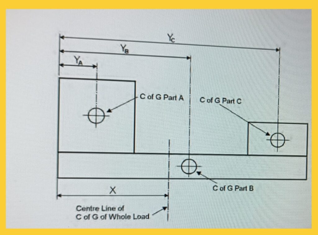
(Wa + Wb + Wc) X = Wa Ya + Wb Yb + Wc Yc
the unknown distance X can then easily be found.
Once the position has been estimated, it should be marked in some way (e.g., with chalk or sticky tape) to guide the operative when attaching the slings.
This calculation will determine the position of the center of gravity in one plane only. By applying the same method to the other two planes, the precise position can be determined.

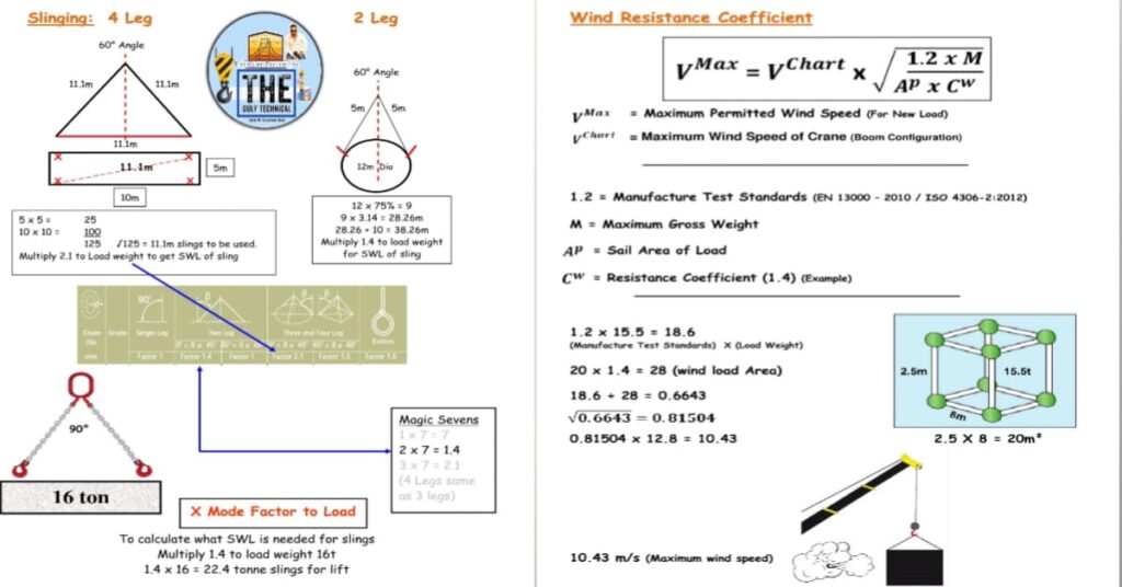
Value of π
π is approximately equal to 3.142
Weight Conversion:
1 ton (US) = 2000lb = 907.185kg
1 tone (metric) = 1000kg = 0.9842tons (imperial) = 2204.6lb (imperial)
Force Conversion
1 tf (US) = 2000lbf = 8.896 kN
1 ton (metric) = 2204.6lbf = 9.806 kN
Ensure the compatibility of units in all calculations.
CENTER OF GRAVITY (C of G):
The center of gravity is the place at which the body’s whole weight can be considered concentrated; alternatively, it can be thought of as the point at which the body’s components perfectly balance one another.
With a regularly shaped load, the position of the center of gravity can easily be judged by measuring out the midpoint in each direction. For more complex shapes, however, it may be necessary to estimate the center of gravity of the various parts of the load and then combine them to get the center of gravity for the whole.
The position of the line through which the center of gravity of the entire object acts, which is an unknown distance X from the given point, can be found by taking moments about a given point, such as one end, and estimating the weights of the three parts A, B, and C, which are, respectively, Wa, Wb, and Wc.